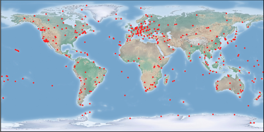
The IGS collects, archives, and freely distributes Global Navigation Satellite System (GNSS) observation data sets from a cooperatively operated global network of ground tracking stations. IGS stations provide continuous tracking using high accuracy receivers and have data transmission facilities allowing for rapid (minimally: daily) data transmission to the data centers.
IGS Guidelines
The IGS network is a collection of heterogeneous stations operated by many different organizations pooling their resources under the IGS umbrella for the common good. Stringent rules are inconsistent with the voluntary nature of the IGS. However, participating stations must agree to adhere to the standards and conventions contained herein, which ensure the consistent high quality of the IGS network and products. Of particular importance to the IGS is the stable, long-term operation of the network.
IGS stations provide continuous tracking using high accuracy receivers and have data transmission facilities allowing for rapid (minimally: daily) data transmission to the data centers. The stations must meet physical and operational requirements. The latest version of such standards are fully described here: Guidelines for Continuously Operating Reference Stations in the IGS.
Site Log Manager 2.0
The International GNSS Service (IGS) collects, archives, and freely distributes Global Navigation Satellite System (GNSS) observation data sets from over 200 global agencies that make up a network of ground tracking stations. The Site Log Manager 2.0 (SLM 2.0) is a software system designed to allow station operators to securely manage the metadata across the GNSS ground based sites. The SLM 2.0 is a vital and tremendous service to the global GNSS community. Our primary goal for the SLM 2.0 is to maximize the reliability, accuracy, and searchability of site log metadata information. This will be achieved through easy moderation and review, automation, structured data, and broad adoption.
Access to the Site Log Manager 2.0 is restricted to authorized users such as IGS station operators. If you are an IGS station operator and need access, please contact the IGS Network Coordinator at cb@igs.org.
Key New Features include:
- New and improved user interface – designed a clean, modern interface that better shows key items for the user, so that they can get to their destination or complete their actions with ease, as well as restructured sections/pages for a more streamlined flow between features
- Using the latest technology – developed the new system with a more robust programming language and database to allow for sustainability and make way for future features such as GeodesyML, interoperability, and command-line API
- Improved Editing – developed easy to edit form fields with the ability to edit past sections
- Improved Validation – developed better validation checks when a user adds or edits station metadata to ensure the station metadata is as accurate as possible
- New Alerts/Notifications – created a new alert/notifications system where users will able to view any validation errors or notes from the SLM admin/moderator
- New List/Map View – created a new and improved station list to view, search, sort, and filter through stations, and be able to view the station locations on an interactive 3D global map
- Open Source – the new SLM is open source software issued under the MIT license. It is free to use and has a no-fork architecture that allows significant adaptations without the need to change core code. We welcome contributions!
- Stronger Validation – stronger validation coupled with a more strongly typed data model will increase the quality and accuracy of site log information over time
- GeodesyML support – station metadata can now be uploaded and downloaded in a GeodesyML format. To learn more about GeodesyML, visit the GeodesyML website

Monumentation Design and Implementation Recommendations
Table 1: Considerations for Monumentation
| Desired Monument Characteristics | Parameters Affecting Monument | Characteristics of a Good Monumentation Site | Good Practice in Design of Monument |
|
|
|
|
Table 2: Types of monuments and examples of each
| Monument Type | Description | Organizations | Characteristics | |
| Pier | C-Bar Reinforced Concrete | National Geodetic Society (NGS) |
|
|
| Rebar Reinforced Concrete |
|
|
||
| H-beam | New Mexico State Highway and Transportation Department |
|
||
| Helical | United States Geological Survey (USGS) |
|
||
| Rod | Stainless Steel | WCDA |
|
|
| Metal Rod Brace |
|
|||
| Invar rod encased in concrete | UNAVCO |
|
||
| Mast | Rohn Tower | U.S. Coast Guard |
|
|
| Stainless Steel | GPS Earth Observation Network of Japan (GEONET) | |||
| Chain Link Fence Post |
|
|
||
| Building | Rooftop |
|
|
|
| Wall Mounted |
|